Background
Previous tests provided results using measurements of duration, battery terminal voltage, and load resistances. Those results indicated that the total initial energy stored in the test circuit's rechargeable battery could be effectively 'recycled' by feeding a proportion of the input energy back to the battery from temporary storage within the circuit
Energy-to-work conversion ratios in the range 170-200% were observed
The circuit operates with all the usual inefficiencies but the duration of its operation becomes extended due to the real-time recharging of its supply battery
Thermal Profile testing
These latest tests confirm the ability to recycle some of the original energy, by measuring the thermal activity of the total system:
- the reference test measures the temperature at the load resistor, against time, when all the input energy is dissipated directly within the circuit (results labelled as 'No F/b');
- the active test measures the temperature at the load resistor, against time, for the arrangement where some energy is used to partially recharge the supply battery (results labelled as 'With F/b')
The temperature of the load resistor is related to the current it carries - the value of the heat energy dissipated by the resistor is given by the product of the resistance with the square of the current and with time
The circuit has been arranged in such a way that the total supply current for the circuit is the same for both the reference test and the active test. If the results show that the same temperature is achieved at the load resistor for the duration of both tests, then the comparative duration values will indicate whether or not the circuit arrangement with energy feedback to the battery (See Fig. 1) can effectively operate for longer (ie. produce more work) than the circuit which just dissipates all the energy supplied from the battery into the circuit in one pass
 |
| Fig. 1 - Ringwood Energy Recycler Block Diagram |
Test procedure
The circuit has been simplified and re-arranged to provide for measurement of temperature on a single 27 ohm load resistor which is in the input path of the total current supplied to the circuit (See Fig 2.). The supply battery voltage has been increased to 5.2V (nominal) in order to improve the significance of the temperature rise compared with the ambient. The temperature values, deltaT, presented on the graph represent the difference between the temperature probe, monitoring the load, and the sensor monitoring the ambient temperature
The circuit is tested in two configurations:
- (Reference test) the output pulse from the BAT42 diode is connected to the cathode of a 5v1 zener diode, to dissipate the pulse energy within the circuit;
- (Active test) the output pulse from the BAT42 diode is connected to the +ve terminal of the battery, where it provides a partial recharge with the pulse energy
The switch S1 shown in Fig 2. provides these 2 test arrangements, a) and b)
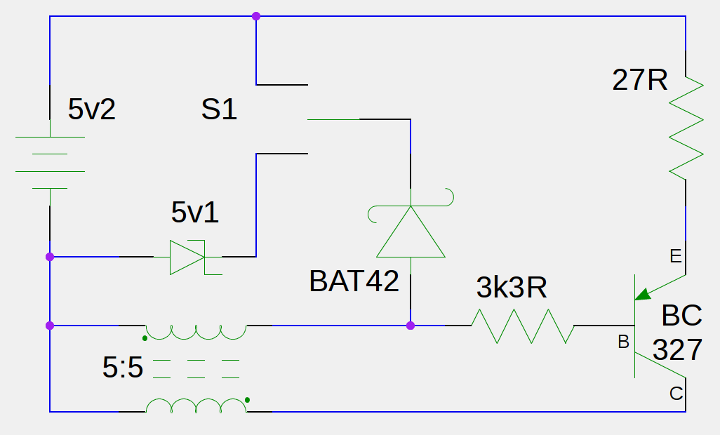
Fig. 2 - Test circuit used to obtain thermal output profile
The circuit and battery are completely enclosed within a metal container, which is lined with a layer of heat-insulation. A thermistor temperature probe is fixed to the 27 ohm load resistor;
A second thermistor sensor records ambient temperature (within the datalogger interface)
Results
The numerical results, obtained from the data spreadsheet calculations, show that for a full discharge of energy from the battery in each case:-
- (Reference test)
sustained an average deltaT of 9.92 degC for a total of 8.4 hours
- (Active test)
sustained an average deltaT of 9.98 degC for a total of 10.6 hours
(The test durations are measured between mid-point values of the rising and falling edges of each temperature profile; the temperature profile for each test has been aligned then at the selected point for that test, to provide a direct comparison of their respective durations)
These results are presented graphically in Fig 3:
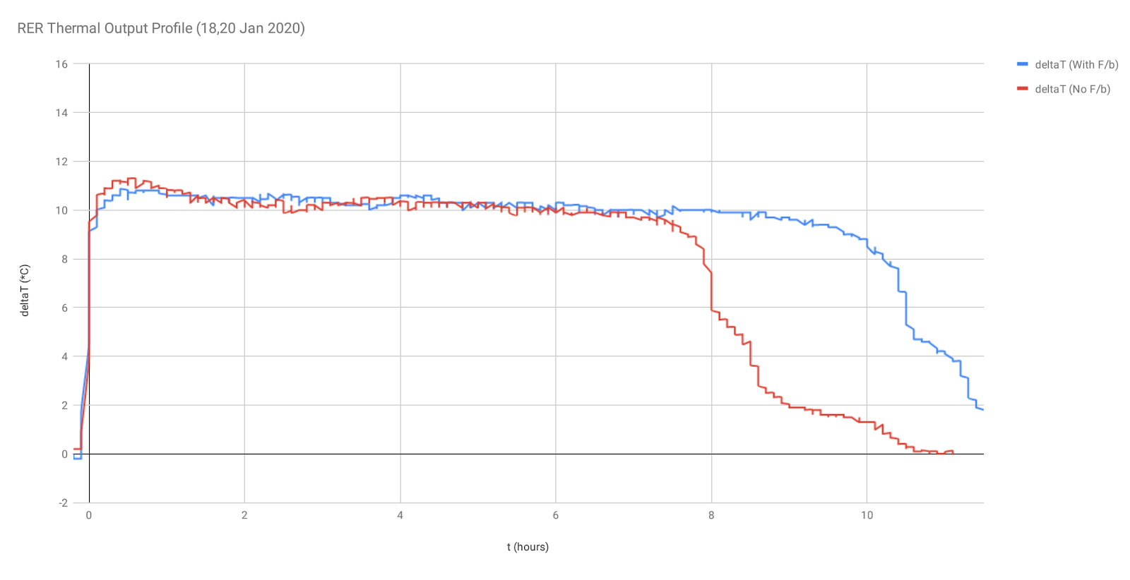
Fig. 3 - Thermal Output Profile results
A separate discharge test of the same battery, using a 68 ohm resistor, produced a value of 10650 Joules for the total energy stored by the battery when fully charged; using this value, the average current drawn by both the reference and the active test circuits is calculated to be approx 70mA
Conclusions
The results confirm that both the reference test and the active test are operating with the same average supply current, as evidenced by close agreement of the average temperatures measured at the load resistor in the supply path
Since the active test duration is longer than the duration of the reference test, the circuit with feedback of energy to its supply battery is shown to have increased the total amount of work converted from that battery by a factor of (10.6 / 8.4) = 1.26
These results confirm the results of previous testing (mentioned above); the initial energy obtained and converted from the battery (10650 Joules) and temporarily stored within particular circuit components can then be used to partially recharge the supply battery in real-time and extend the total amount of work which is converted by the whole system (13450 Joules)
The example arrangement tested here effectively extended the total amount of work converted from the supply battery to 126%
No comments:
Post a Comment